ROTORK Power Equipment - Hydraulic Power Units
- Hydraulic Power Units
- Used
- ROTORK HPU Bifold Group 3,800L
- -
- Tarragona , 43153 ESP
25000$25,000 EUR
Escrapalia
- Hydraulic Power Units
- Used
- ROTORK HPU Bifold Group 3,800L
- -
- Tarragona , 43153 ESP
Auction Details
General Specs
2014
1
Used
No
Detailed Description
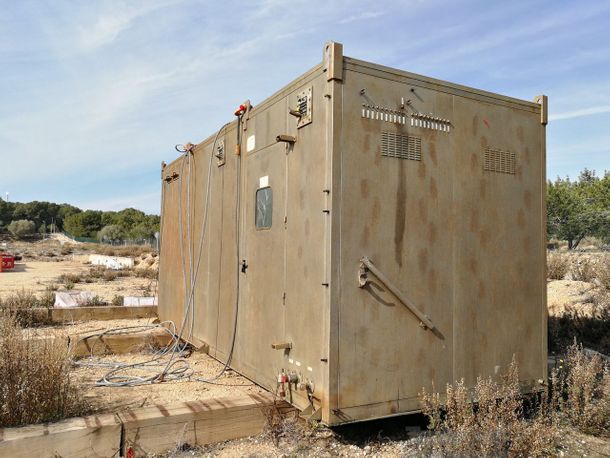
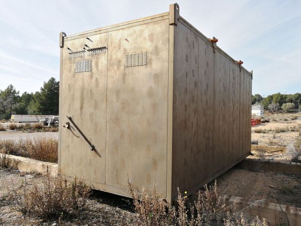
Hydraulic Power Units - Online auction of a hydraulic power unit (HPU) manufactured in 2014 for the control of subsea wells and from a major energy multinational.

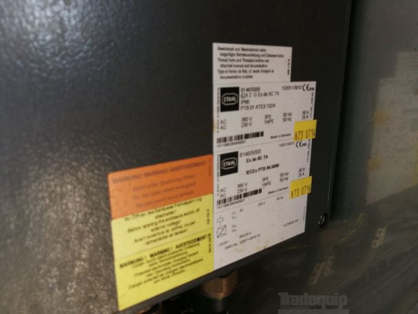
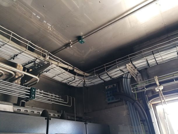
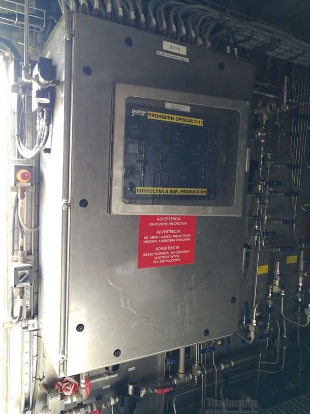
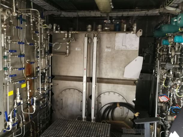
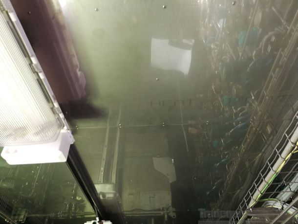
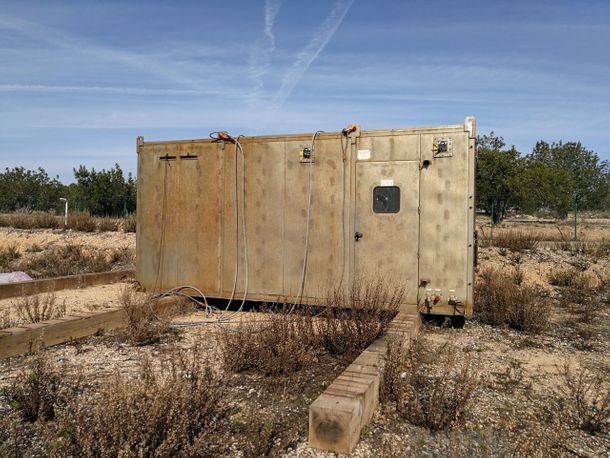
Container made of stainless steel. ATEX

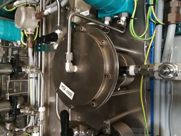
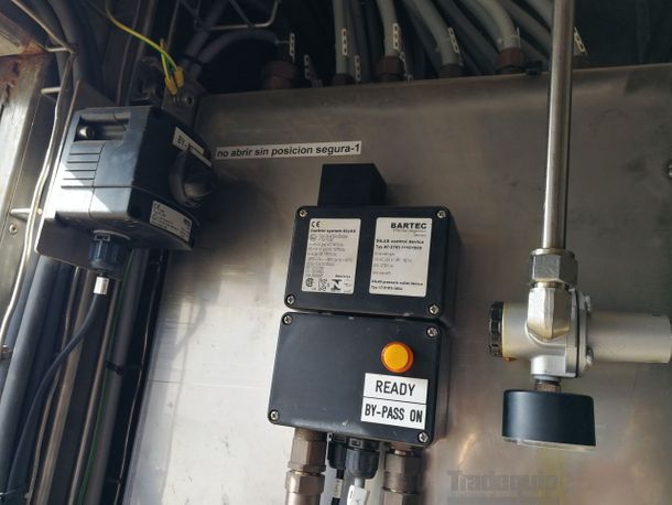
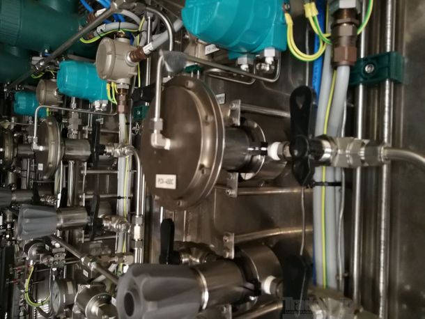
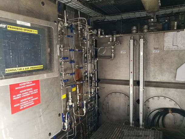
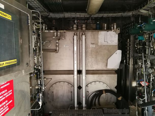
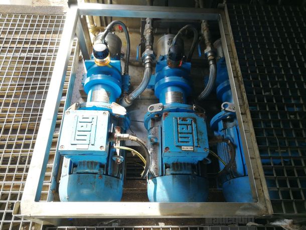
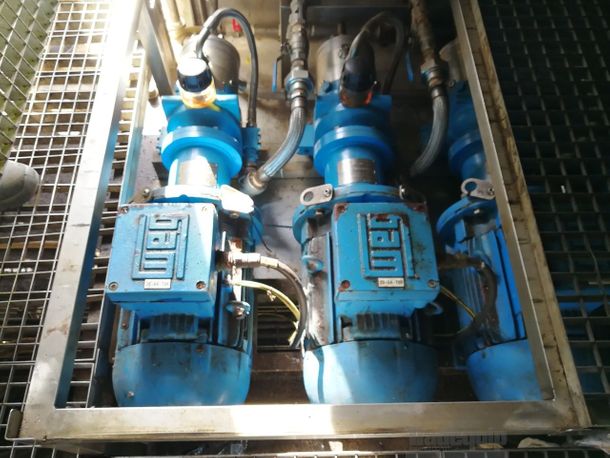
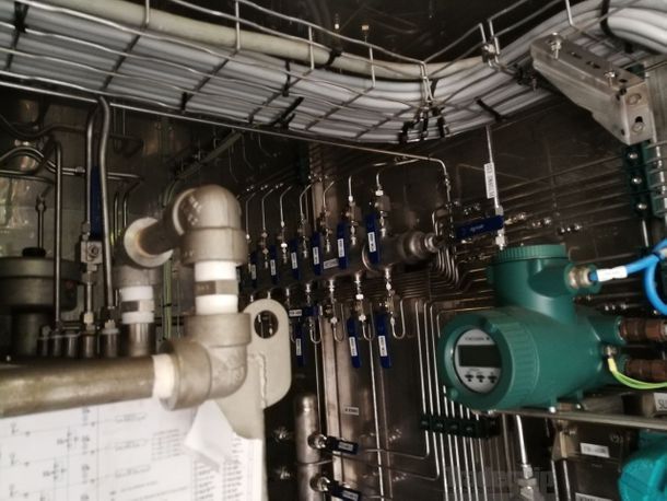
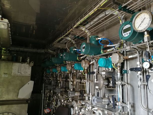
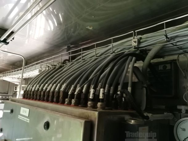
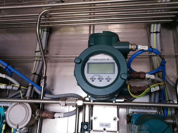
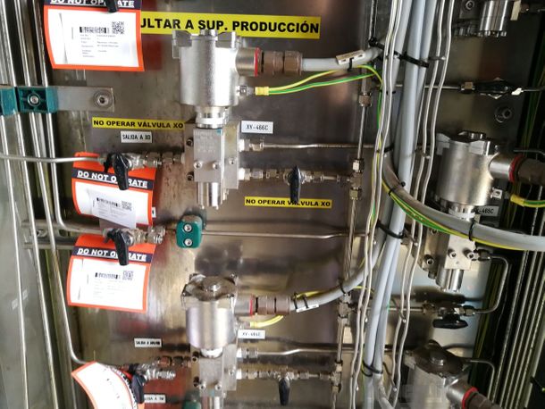
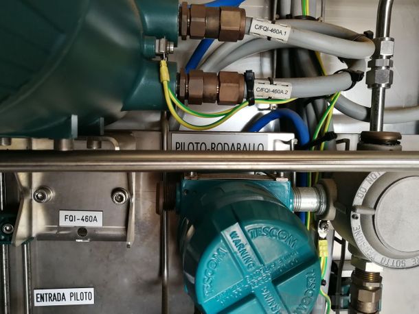
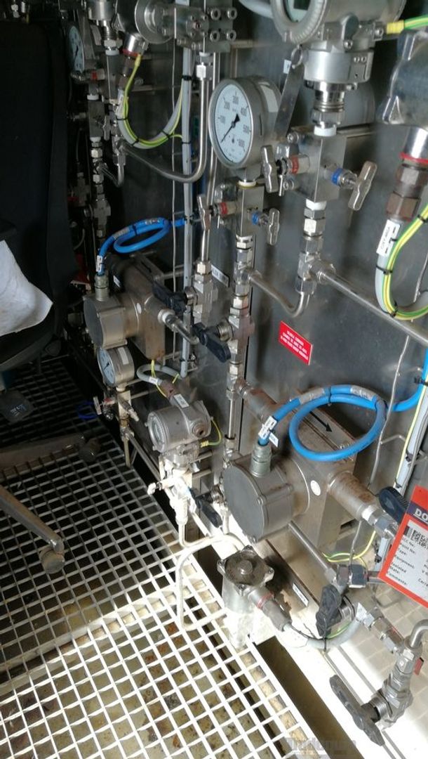
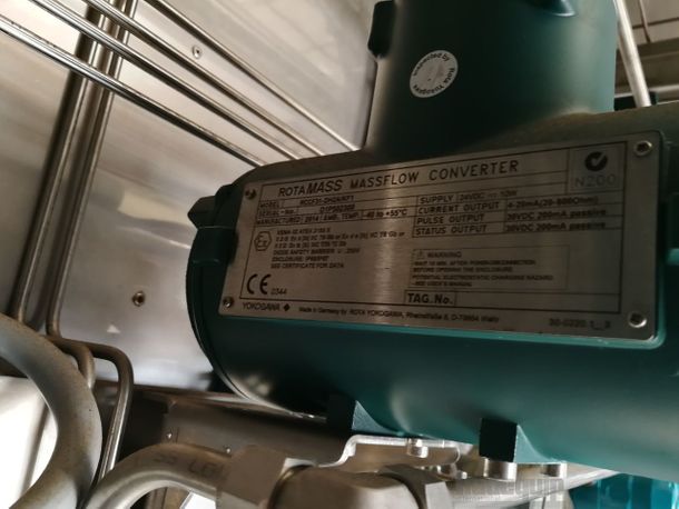
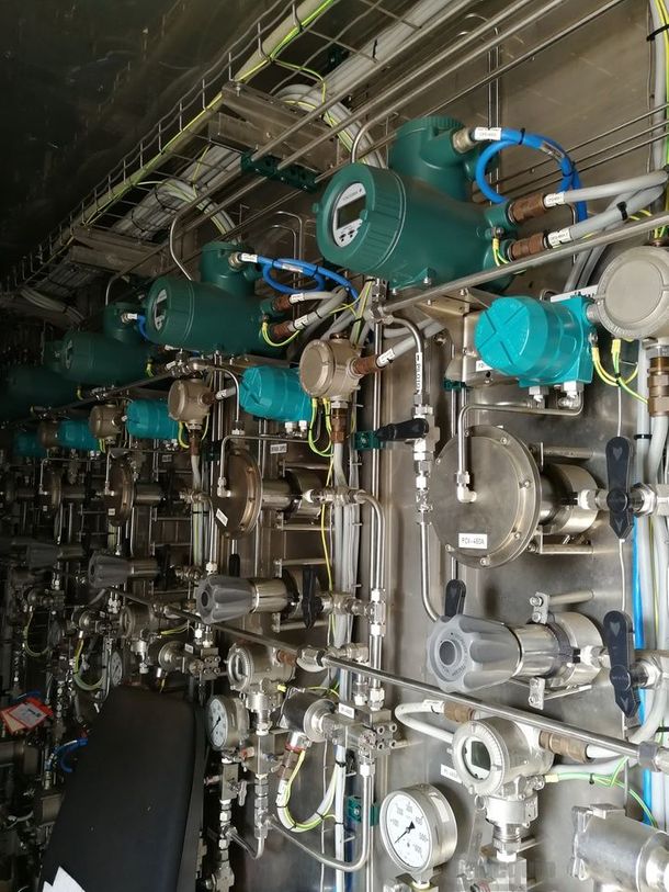
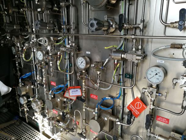
Inside this house, the panel consists of some equipment (pumps, manual valves, tanks, solenoid valves, regulating valves, etc.), which, together, allow the control of the subsea wells.

Broadly speaking, we can define three subsystems integrated into it:

1) Supply and return tank system
2) Supply System
3) Pilot System


EQUIPMENT DESCRIPTION

TANKS
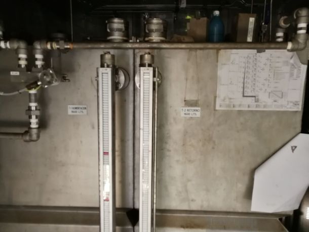
The system is hydraulic and as such, must store and control the hydraulic fluid (fresh water mixture (95%) and RENOSAFE HFAS 12 (5%)). Two tanks with a capacity of 1600 liters each are used for storage, called the T-1 feed tank and the T-2 return tank. Their names are given by their functionality: - T-1: feeds the suction of the pressure pumps of the Supply and Pilot lines. - T-2: recovers all the fluid vented through the different valves of the system; It is also where the mixture that the operators will make is prepared. These tanks have manual valves and solenoid valves that allow them to communicate or isolate themselves from all other systems.


PUMP & FILTERS
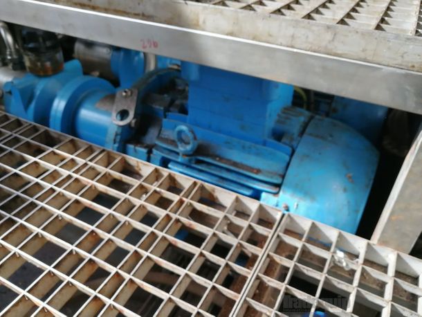
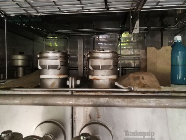
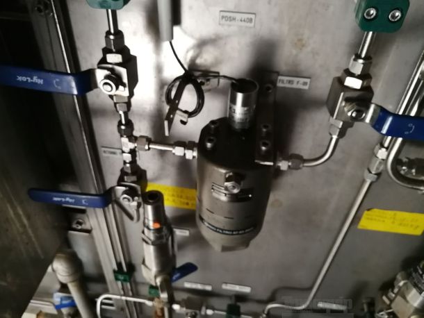
There is also a 20-GA-75 recirculation pump which allows us to pass the fluid through filters F-01 or F-02 (sieve of 3μm each) so that we free the fluid from unwanted particles. A larger space F-07 mesh filter is also available to the suction of this pump, to protect the pump from unwanted suctions.

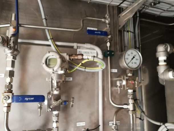
MANUAL VALVES
The purpose of manual valves is to allow maintenance operations as well as special operations other than those of normal work.

SOPENDENO VALVES
The purpose of solenoid valves is to enable normal working operation from the control system. These valves can also be operated from the Monitoring System, in the control room, by the panel operator. Below is a breakdown of the usefulness of each of the valves.


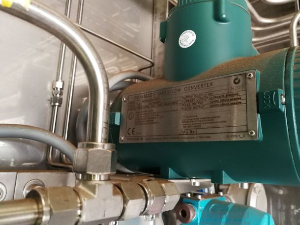
INSTRUMENT DESCRIPTION
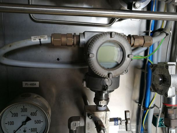
Each tank has an analogue and digital level wired to the Control System, which will indicate the levels of the tanks at all times in the Monitoring System.


